
So, how do I make the board into a solid, with the holes being holes in it? If I select all, and extrude, what I get is extrusions of these elements, ie lines and circles in the Z direction. I've read other posts, and I'm not even sure if I need to convert to a sketch to do this. ( I did NOT convert it into a sketch, as I'm not really sure how to do this at this point. I'm in the FreeCAD Part workbench, and can import the DXF okay, I've attached a screen shot. I use a printed circuit board program called Diptrace, and have outputted from it a DXF file containing the board outline and holes only.

I have a very simple (I think) problem to solve. I'm a bit confused about the usages of all of the different workbenches, and trying to figure it all out. Using PCB text position not yet - it requires using additional structure and testing it, so keep it for the next minor update after 4.0.New FreeCAD user here.

I will try to fix this also - should not be hard, correct RefDes - 100% but with position - some conflicts are possible, maybe better to keep library position or optional - will check.ĭisplaying correct text at once has been fixed.

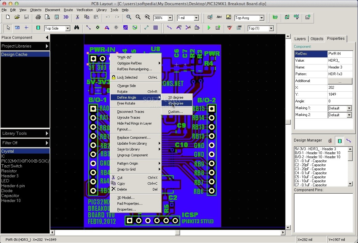
R changes back to R1), but stays in its default location. Step 4 - Open and then close the Component Properties dialog window and observe that the reference designator's numerical assignment returns (e.g. R1 changes to R) and moves back to its default location. Step 3 - Update the component from the library and observe that the reference designator loses its numerical assignment (e.g. Step 2 - Move its reference designator to a location that is different from its default. Step 1 - Create a component where text has been assigned to represent the reference designator (Show > RefDes) and place the component on a PCB. I just remembered one more bug that shows up after assigning text to the reference designator.


 0 kommentar(er)
